
Introduction
A brief view of how pavement design, construction and performance has evolved should help provide perspective on present and, possible, future practice. This short view into the past will start with the Romans, then move on to the Macadam and Telford era, then into the first 150 years of asphalt and portland cement concrete pavement. The evolution of pavement design will emphasize the U.S.A. and the U.K. a bit more than for other parts of the world.
Roman Roads
In fairness, the Carthaginians are generally credited with being the first to construct and maintain a road system (about 600 B.C.) according to Tillson [1900]. The Romans eventually decided that their neighbors across the Mediterranean were a bit of a threat to the empire destroying Carthage in 146 B.C. (The Carthage ruins are located in Tunisia (Northern Africa) next door to Algeria (on the left) and Libya (on the right — so to speak).) It is suggested that the Romans took up the practice of a military road system from the Carthaginians. It is estimated that the Romans built about 87,000 km of roads within their empire (about equal to the length of the U.S. Interstate system).
Apparently, there is no record of “traditional” roads in the U.K. prior to the Romans [Collins and Hart, 1936]. For the most part, the main Roman roads in the U.K. (total of about 4 100 km) was for military purposes in that they connected camps which were about 30 km apart (or about one day’s march) [Collins and Hart, 1936; Rose, 1935; Leger, 1875]. Since the primary purpose of these roads was for foot soldiers, the roads were straight, but virtually without regard to grade. They generated high noise levels, were rough and labor intensive (slave and “statue” labor often used).
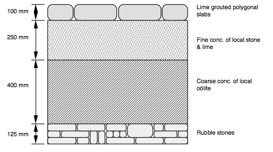
The Roman design for their primary U.K. roads generally consisted of four layers (top to bottom) as follows [Collins and Hart, 1936]:
- Summa Crusta (surfacing): Smooth, polygonal blocks bedded in underlying layer.
- Nucleus: A kind of base layer composed of gravel and sand with lime cement.
- Rudus: The third layer was composed of rubble masonry and smaller stones also set in lime mortar.
- Statumen: Two or three courses of flat stones set in lime mortar.
The total thickness was as much as 0.9 m and road widths of 4.3 m or less. An illustration of Roman pavement structure near Radstock, England, is shown as Figure 1. Roman roads in some countries have been up to 2.4 m thick. These structures had crowned (sloped) surfaces to enhance drainage and often incorporated ditches and/or underground drains.
As one might expect, Roman road building was varied to suit local conditions and materials — not unlike today actually. The Romans departed the U.K. about AD 406. Road design and construction languished for about 1,200 years thereafter.
Roman road construction was not inexpensive. Updated construction estimates of the Appian Way in Italy are about $2,000,000 per km (updated estimates following Rose [1935] and Leger [1875]).
The oldest known road in the U.K. is near the River Brue in southwestern England [Coles, 1989]. Actually, the “road” is a 6,000 year old walkway which was discovered in 1970 in a peat bog. The construction of the road coincides with the arrival of the first farmers in the U.K. about 4,000 B.C.
Telford and Macadam
Telford
Thomas Telford (born 1757) served his apprenticeship as a building mason [Smiles, 1904]. Because of this, he extended his masonry knowledge to bridge building. During lean times, he carved grave-stones and other ornamental work (about 1780). Eventually, Telford became the “Surveyor of Public Works” for the county of Salop [Smiles, 1904], thus turning his attention more to roads.
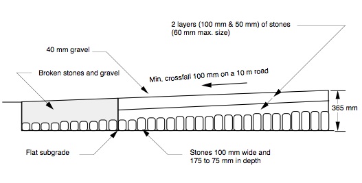
Telford attempted, where possible, to build roads on relatively flat grades (no more than 1 in 30) in order to reduce the number of horses needed to haul cargo. Further, the pavement section was about 350 to 450 mm in depth and generally specified in three layers. The bottom layer was comprised of large stones (100 mm) wide and 75 to 180 mm in depth) [Collins and Hart, 1936]. It is this specific layer which makes the Telford design unique [Baker, 1903]. On top of this were placed two layers of stones of 65 mm maximum size (about 150 to 250 mm total thickness) followed by a wearing course of gravel about 40 mm thick (refer to Figure 2). It was estimated that this system would support a load corresponding to 88 N/mm (500 lb per in. of width).
Macadam
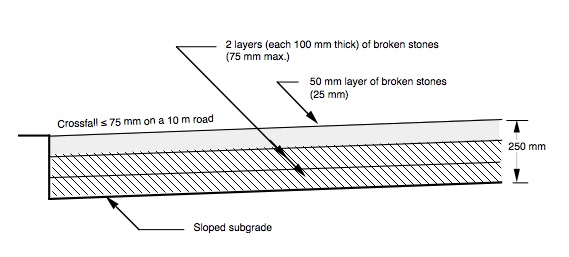
John Macadam (born 1756) observed that most of the “paved” U.K. roads in early 1800s were composed of rounded gravel [Smiles, 1904]. He knew that angular aggregate over a well-compacted subgrade would perform substantially better. He used a sloped subgrade surface to improve drainage (unlike Telford who used a flat subgrade surface) on which he placed angular aggregate (hand-broken, maximum size 75 mm) in two layers for a total depth of about 200 mm [Gillette, 1906]. On top of this, the wearing course was placed (about 50 mm thick with a maximum aggregate size of 25 mm) [Collins, 1936]. Macadam’s reason for the 25 mm maximum aggregate size was to provide a “smooth” ride for wagon wheels. Thus, the total depth of a typical Macadam pavement was about 250 mm (refer to Figure 3). An interesting quote attributed to Macadam about allowable maximum aggregate sizes was that “no stone larger than will enter a man’s mouth should go into a road” [Gillette, 1906]. The largest permissible load for this type of design was estimated to be 158 N/mm (900 lb per in. width).
In 1815, Macadam was appointed “surveyor-general” of the Bristol roads and was now able to use his design on numerous projects. It proved successful enough that the term “macadamized” became a term for this type of pavement design and construction. The term “macadam” is also used to indicate “broken stone” pavement [Baker, 1903]. By 1850, about 2,200 km of macadam type pavements were in use in the urban areas of the UK.
Macadam realized that the layers of broken stone would eventually become “bound” together by fines generated by traffic. With the introduction of the rock crusher, large mounds of stone dust and screenings were generated [Gillette, 1906]. This resulted in use of such fines resulting in the more traditional dense graded base materials which in turn produced pavement thicknesses as thin as 100 to 150 mm.
The first macadam pavement in the U.S. was constructed in Maryland in 1823.
Early Thickness Trends
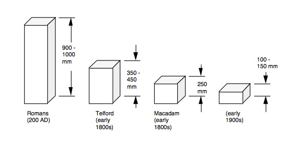
Thus, we have seen pavement structures decrease from about 0.9 m (3 feet) for Roman designs to 350 to 450 mm for Telford designs, to about 250 mm for Macadam designs, to 100 mm at about the turn of the century (refer to Figure 4). (Naturally, the thinnest pavements were not always used.) The Massachusetts Highway Commission standard cross-section for macadam construction was 150 mm thick as reported by Gillette in 1906. This thickness was also used on New York state roads at about that time.
 Up to the early 1900s, the design emphasis was placed on the use of fixed standards occasionally modified for local soil conditions. Further, the need for more durable pavements was mandated by the changing vehicle fleet. The following partial quote by L. W. Page, Director of U. S. Office of Public Roads (contained in a 1907 report [Judson, 1908]) illustrates the problem:
“…The existence of our macadam roads depends upon the retention of the road-dust formed by the wearing of the surface. But the action of rubber-tire motor-cars moving at high speed soon strips the macadam road of all fine material, the result being that the road soon disintegrates…”
Early Bituminous Pavement
Tar Macadam
It appears that the first tar macadam pavement was placed outside of Nottingham (Lincoln Road) in 1848 [Collins and Hart, 1936; Hubbard, 1910]. At that time, such pavements were considered suitable only for light traffic (not for urban streets). Coal tar (the binder) had been available in the U.K. from about 1800 as a residue from coal-gas lighting. Possibly this was one of the earliest efforts to recycle waste materials into a pavement!
Soon after the Nottingham project, tar macadam projects were built in Paris (1854) and Knoxville, Tennessee (1866) [Hubbard, 1910]. In 1871 in Washington, D.C., a “tar concrete” was extensively used. Sulfuric acid was used as a hardening agent and various materials such as sawdust, ashes, etc. were used in the mixture [Hubbard, 1910]. Over a seven-year period, 630,000 m2 were placed. In part, due to lack of attention in specifying the tar, most of these streets failed within a few years of construction. This resulted in tar being discredited, thereby boosting the asphalt industry [Hubbard, 1910]. However, some of these tar-bound surface courses in Washington, D.C., survived substantially longer, about 30 years. For these mixes, the tar binder constituted about 6 percent by weight of the total mix (air voids of about 17 percent). Further, the aggregate was crushed with about 20 percent passing the No. 10 sieve. The wearing course was about 50 mm thick.
As a side note, the term “Tarmac” was a proprietary product in the U.K. in the early 1900s [Hubbard, 1910]. Actually it was a plant mixed material, but was applied to the road surface “cold.” Tarmac consisted of crushed blast furnace slag coated with tar, pitch, portland cement and a resin.
Sheet Asphalt
Sheet asphalt placed on a concrete base (foundation) became popular during the mid-1800s with the first such pavement of this type being built in Paris in 1858. The first such pavement placed in the U.S. was in Newark, New Jersey, in 1870. Baker [1903] describes this pavement system as (1) a wearing course 40 to 50 mm thick composed of asphalt cement and sand, (2) a binder course (about 40 mm thick) composed of broken stone and asphalt cement, and finally, (3) a base layer of hydraulic cement concrete or pavement rubble (old granite blocks, bricks, etc.). Generally, the concrete layer was 100 mm thick for “light” traffic and 150 mm thick for “heavy” traffic [Baker, 1903]. The final thickness was based on the weight of the traffic, the strength of the concrete and the soil support.
Bitulithic Pavements
In 1901 and 1903, Frederick J. Warren was issued patents for the early “hot mix” paving materials. A typical mix contained about 6 percent “bituminous cement” and graded aggregate proportioned for low air voids. Essentially, the maximum aggregate size was 75 mm ranging down to dust. The concept was to produce a mix which could use a more “fluid” binder than used for sheet asphalt. This material became known as “Bitulithic.”
More specifically, Warren was issued eight U.S. patents in 1903 which were:
- Patent 727,505 Pavement
- Patent 727,506 Asphaltum and its Manufacture
- Patent 727,507 Asphalt Composition and its Manufacture
- Patent 727,508 Pavement
- Patent 727,509 Method of Constructing and Laying Street Pavements or Roadways
- Patent 727,510 Street Sheet Pavement or Roadway
- Patent 727,511 Street Sheet Pavement or Roadway
- Patent 727,512 Renewal of Old Street — Pavements
All of these patents were filed between May 16, 1901, and April 14, 1902. A review of the associated patent claims reveals that Warren, in effect, patented asphalt concrete, the asphalt binder, the construction of asphalt concrete surfaced streets and roads, and the overlayment of “old” streets. It seems that he covered “all the bases” with these patents. Some might argue that Patent 727,504 issued to Edward Walker of Warren, Pennsylvania, was actually just as important — the ice cream freezer! Warren’s actual patent claim for 727,505 follows [U.S. Patent Office, 1903]:
“A street-pavement mixture composed of mineral ingredients ranging in grades from three inches down to impalpable powder, from fifty to eight per cent, of such mineral ingredients lying between one-fourth inch and three inches in diameter, in combination with a bituminous binder.”
In 1910 in Topeka, Kansas, a court ruling stated that asphalt concrete mixes containing 12.5 mm maximum size aggregate did not infringe on Warren’s patent (727,505) [Steele, 1986]. Thus, asphalt concrete mixes thereafter were more oriented to the smaller maximum aggregate sizes. (A “fine aggregate” or “modified Topeka asphaltic concrete” is mentioned in a 1926 Standard Oil Co. of California publication [Goodyear Tire and Rubber Company, 1985]. The mixture consisted of 30 percent graded crushed rock or gravel (all passing 12.5 mm sieve, about 58 to 62 percent sand (material passing 2.0 mm and retained on 75 µm), 8 to 12 percent filler (material passing 75 µm sieve). This mixture required 7.5 to 9.5 percent asphalt cement.)
Warrenite-Bitulithic was invented in 1910 by a retired employee of Warren Brothers. It consisted of a thin, approximately 25 mm thick layer of sheet asphalt placed on top of the hot, uncompacted Bitulithic (Crawford [Crawford]). The advantage of this system is that the large aggregate of the Bitulithic mixes were not exposed directly to heavy, steel rimmed wheels which cracked the aggregate, eventually resulting in mix degradation.
By 1920, Warren’s original patents had expired in the U.S. [Oglesby, 1962].
U.S. West Coast
A Standard Oil Co. of California publication [1985] noted that the first asphalt concrete pavement on the West Coast was placed in 1894. Further between 1914 and 1926, 95 percent of such pavements were 125 mm or less in total thickness (75 to 87.5 mm of asphalt base and 37.5 to 50 mm of asphalt concrete surfacing). In 1921 for the states of Washington, Oregon, California, Nevada, and Arizona, approximately 770 lane-kilometers (3.6 m lanes) of asphalt concrete pavement were constructed. By 1925, the annual constructed lane-kilometers had increased to 1530.
A interesting quote from the 1926 Standard Oil Co. of California publication [1985] seems to be repeated quite often today:
“These pavements are today [1926] giving excellent service … notwithstanding the fact that these pavements were not originally designed for the severe conditions imposed by the heavy and fast modern motor traffic.”
City of Seattle
In the 1910 City of Seattle Standard Specifications, it was stated that an “asphalt pavement shall consist of:
- Wearing course 50 mm thick,
- Binder course 25 mm thick, and
- Concrete base.
Further, the asphalt cement in the asphalt paving mixture
“shall be a solid, natural bitumen obtained from some natural deposit that has been in use in the paving industry for at least five (5) years.”
By 1919, the Seattle Standard Plans and Specifications contained the same definition for asphalt pavement (AC over PCC) but the asphalt binder could be
“either a solid natural bitumen or a California oil asphalt that has been in use in the paving industry for at least five (5) years.”
Early Asphalt Cements

It should be noted at this point that an early source of asphalt binder in the U.S. was from Trinidad (near the coast of Venezuela). Trinidad supplied about 90 percent of all asphalt (worldwide) from 1875 to 1900 [Baker, 1903]. The asphalt was produced from a “lake” with a surface area of 465,000 m2 (46.5 ha or 115 acres) and a depth of about 24 m. It was estimated by Tillson in 1900 that this “lake” contained about 8,000,000 metric tons of “asphalt” (compare this against 1990 consumption in Europe and the U.S. of approximately 40,000 000 metric tons of asphalt binder). This asphalt, once free of water, was too “hard” to use in paving [Krchma and Gagle, 1974]. In fact, Trinidad lake asphalt, when loaded bulk into a ship, would fuse to the point that removal required chopping. It appears that the earliest use of asphalt binder in the U.S. was about 1874 for a project built in Washington, D.C. This binder was a combination of Trinidad lake asphalt and a flux oil distilled from crude oil. Without question, these early asphalt binders were quite variable making structural design somewhat challenging. By the 1880s, asphalt binders were regularly produced in California and by 1902 in Texas as well. It was not until 1907 that crude oil-based asphalt surpassed “natural” asphalt production [Krchma and Gagle, 1974].
An early Standard Oil Co. of California asphalt cement specification contained four original penetration ranges (at 25 °C) of 31-40, 41-50, 51-60, and 61-70. Thus, it appears that some of the early asphalt cements were a bit “harder” than generally used today.
Early Portland Cement Concrete Pavments
At the turn of the century (1900), cements were categorized as “natural” or “artificial.” Natural cements were made directly from specific rock. Artificial cement was made from proportioned ingredients and became known as “Portlands” (named after the natural limestone rock found on the Portland Bill, which is a small projection of land into the English Channel near Weymouth on the southern U.K. coast). The first true portland cement was produced in the U.K. about 1824 (actually portland cement was patented in 1824 by Joseph Aspdin, a bricklayer in Leeds, U.K.) and in the U.S. about 1865 (from Tillson, 1900).
Interestingly, portland cement concrete (PCC) was not used as a pavement wearing course much until after about 1910 (Agg, 1940); however, it was regularly used as a “stiff” base to support other wearing courses such as wooden blocks, bricks, cobble stones, etc. One likely reason for this was the lack of a consistent specification for the early cements. Tillson in 1900 summarized over 109 separate specifications on portland cement fineness. Add to this confusion the fact that natural cements were widely used as well (about 60 percent of total cement consumption in 1898). Further, PCC hand mixing was still common in 1900 which undoubtedly restricted productivity and accurate proportioning. By 1900 (as reported by Tillson), it was common to volumetrically proportion PCC as a 1:2:4 or 1:2:5 (cement : sand : coarse aggregate).
A quote by Baker (1903) is of interest:
“This form of road surface is not likely to come in general use owing to its cost and slipperiness when laid as are sidewalks, and its cost and lack of durability when laid like the foundation of a pavement.”
Further light is shed on the use of PCC as a surfacing layer by Hubbard (1910):
“If motor traffic alone were to be considered, a road built entirely of cement concrete might prove the most satisfactory and economical form for the future. For mixed traffic (horses and motor vehicles), however, such a road is by no means ideal and as, in spite of the increase in motor vehicles, the number of horse drawn vehicles does not seem to be decreasing…”
A 1916 report by Agg and McCullough to the Iowa State Highway Commission further illustrates some of the issues which held back the use of PCC as a wearing course. These include:
- Low compressive strengths.
- Lack of understanding about the need for longitudinal and transverse joints. A quote from the Agg and McCullough report is helpful: “Expansion and contraction may cause longitudinal cracks but generally, for the ordinary width pavement, placed on a flat subgrade, the liability of cracking from this cause, is remote.”
- Poor inspection.
- Poorly prepared subgrade.
- Inadequate mix design, mixing, consolidation and curing of the PCC.
- Failure to achieve adequate strength gain prior to opening streets to traffic.
A survey reported by Agg and McCullough (1940) of 50 states and municipalities presumably is representative of early 1900s practice. Some of the survey results include:
- Transverse joint spacing: About 50 percent of the agencies used spacings of either 24.9 ft (7.6 m) or 29.9 ft (9.1 m). The shortest spacing was 20.0 ft (6.1 m) and the maximum 100.1 ft (30.5 m).
- Angle of transverse joint with the centerline: Most agencies used a 90° joint but 4 percent used a skewed joint of 60°.
- On protection and testing of cement. These data illustrate the issue of evolving standards for tests and specifications
- American Society of Civil Engineers 22%
- American Society for Testing Materials 40%
- Above slightly modified 20%
- U.S. Bureau of Standards 7%
- Association for Standardizing Paving Specifications 4%
PCC was first used as a base for other wearing courses in London in 1872 (after Tillson, 1900) and in New York in 1888 (base for stone surfacing). According to Collins and Hart (1936), the first use of PCC as a wearing course was in Edinburgh, U.K., in 1872 and Grenoble, France, in 1876; however, one source stated that the first PCC pavement was placed in Inverness, Scotland, in 1865. The first PCC pavement in the U.S. was constructed in 1891 in Bellefontaine, Ohio. This pavement was only 3.0 m wide and 67.1 m long (probably what we would call a “test section” today). In 1909, in Wayne County, Michigan, a PCC highway system was constructed.
The Standard Specifications of the City of Seattle for 1910 and 1911 only mention the use of PCC as a base for other pavement surfaces (such as brick, brick block, asphalt, and stone). The specified mix proportions were set at 1:4:7 (cement : sand : gravel). The Standard Plans and Specifications for the City of Seattle dated May 9, 1919 did provide for PCC as a wearing course. The mix proportions were set as 1 : 2 : 3-1/2 (portland cement : sand : gravel). Standard thicknesses ranged from 125 to 230 mm with transverse expansion joints every 9.1 m (and at the end of a day’s work).
The “lean” PCC base (for example, a 1:4:7 mix as used by Seattle) actually was beneficial for brick surfaced pavements (after Jaster et al., 1938):
- less affected by temperature changes,
- due to a lower tensile strength, the cracks which do form are more numerous but narrower,
- expansion joints are not needed (or recommended).
In the book Highway Practice of the USA, the following PCC mileages (centerline presumably) were listed for the U.S.:
By the 1930s, several PCC pavement design features began to evolve. First, typical slab thicknesses were about 200 mm with several states using a thickened edge design (maximum of about 225 mm). Second, it became clear that longitudinal joints should be used every 3.0 to 3.7 m and transverse contraction joints the same (Agg [1940] and Bradbury [1938]).Clearly, not until after 1910 did PCC begin to receive widespread use.
Structural Design
As stated earlier, pavement structural design was achieved by standards or catalogs from the 1800s well into the 1900s. The focus of this review has been on those pavement types which led to asphalt pavement design. It should be noted that portland cement concrete (PCC), up until 1909, was largely used as a base or “foundation” layer for surface course materials such as bricks, wood blocks, sheet asphalt, etc. The year 1909 is noteworthy in the U.S. since this is the time which is generally used to mark the beginning of PCC as a structural wearing course (paving projects in Wayne County, Michigan [Bateman, 1928]).
By 1949 [Public Roads Administration, 1949], the following characteristics of PCC pavement design can be summarized:
- Thickness: The thickened edge cross section was less used since a better understanding of temperature induced stresses was made. Almost all slabs ranged in thickness from 150 to 250 mm.
- Joints: Expansion joints were not needed if contraction joints were frequently spaced (short panels). Before, they were provided every 9.1 to 30.5 m. Expansion joints were expensive to construct properly and difficult to maintain. Contraction joints in plain PCC slabs were recommended every 4.6 to 6.1 m. Load transfer devices (dowel bars) were used by about one-half of the states.
- Reinforcement: The usual practice in 1949 was to place the reinforcement (if used) about 50 to 75 mm below the PCC surface. Generally, transverse joint spacings were increased to 18.3 to 30.5 m. Experiments were under way in New Jersey and Illinois examining the potential for continuously reinforced PCC (0.3 to 1.0 percent of the cross section area for the longitudinal reinforcement).
Up to the 1920s and 1930s, flexible pavement structural design was based mostly on experience based standards. Three reasons have been given for this [Public Roads Administration, 1949]:
- The methods appeared to provide “satisfactory” results for the then prevailing traffic.
- Basic scientific knowledge was lacking.
- The general use of stage construction did not readily lend itself to the evolving scientific methods of design.
In a 1939 paper, Gray overviewed flexible pavement practice for the U.S. states. For hot-mix construction, the typical surface thickness was about 50 mm; however, this ranged from as thin as 19 mm to as thick as 125 mm. The base course types ranged from PCC to asphalt-treated base to gravel. The stabilized bases were generally 150 to 200 mm thick. A typical state such as Kansas applied 50 mm of asphalt concrete over a 175 mm thick PCC slab (urban areas). Thus, by about 50 years ago, pavement thicknesses were beginning to appear a bit closer to what is used today.
Table 1 provides an overview of a few of the flexible pavement design procedures available in 1949 [Gray, 1949]. One can quickly observe that these are mostly empirical relationships, many of which were influenced by the Boussinesq theory of load distribution (such as North Dakota [28]).
Table 1. A 1949 Overview of Flexible Pavement Thickness Design Procedures
[modified after Gray, 1949]
1.  Notes
Notes
2. Legend
t = pavement thickness
P = wheel loads = subgrade bearing
S = assumed settlement of the pavement
C = subgrade modulus of deformation
Cp = pavement modulus of deformation
a = load contact radius
A = load contact area
p = unit capacity pressure
B = cone bearing value (psi)
Traffic

The kinds of loads pavements have been subjected to have varied significantly over the last 200 years. Typical early wagon wheel loads in the U.K. in 1809 are shown in Table 2. This information reveals loads per unit width exceeding that existing on heavy highway vehicles today. In the U.K. during the 1600 and 1700s, restrictive legislation was passed to adapt vehicles to the available pavements (which apparently were in very poor condition) [Collins and Hart, 1936]. An Act of 1751 prohibited wagons on turnpike roads with wheel rims less than 225 mm wide (a bit narrower than today’s heavy truck tires). To suggest the speed of travel during that era, in the mid-1700s, the average speed between London and Bristol was about 13 kph (a distance of 187 km) (after Westinghouse Co., 1904).
Table 2. Weight, Horsepower, and Wheel Characteristics of Vehicles on UK Roads – 1809
(after Collins and Hart [1936])
From a Goodyear publication, the following quote may be of interest [1985]:Wheels continued to evolve. In the early 1800s, Goodyear discovered the hot vulcanization of rubber which made it possible to manufacture solid rubber tires [Collins and Hart, 1936]. The impact of rubber tires can be illustrated by English law. Specifically, the Roads Act of 1920 increased the maximum empty weight of a “heavy traction engine” from 14 to 15.5 tons and, if equipped with rubber types instead of steel wheels, could travel at legal speeds of 19 kph instead of 8 kph [Collins and Hart, 1936]. The pneumatic tire was patented in the U.K. in 1845, but did not come into widespread use until about 1925 (80 years later). The earliest pneumatic tires had major shortcomings in strength and durability [Goodyear Tire and Rubber Company, 1985]. John Dunlap, U.K., greatly improved the design of the pneumatic tire in 1888 although only used on cycles until about 1900. The first pneumatic tire used on a motor vehicle was in 1895 in a race from Paris to Bordeaux [Goodyear Tire and Rubber Company, 1985].
“Actually, many historians have given Goodyear credit for launching the interstate trucking industry in 1917. Of course, there were trucks before then, but virtually all trucking was confined to intercity hauling because of the solid tires of the day which gave a bone-rattling ride and consequent slow speeds.
“In 1917, Goodyear was convinced that trucks would be tremendously more efficient if they rolled on pneumatic tires. When we couldn’t find a trucking company willing to take the gamble, we launched our own line — the Wingfoot Express — with an initial route from Akron to Boston and back ….
“Prophetically, Frank Seiberling, who was Goodyear’s first president, told the U.S. Chamber of Commerce meeting in Chicago just five days after that first 23-day Wingfoot Express run to Boston that, ‘The introduction of the motor truck into our commercial life sounds the death knell for the short line railroad.’
“While the Wingfoot Express was in operation during the ensuing 12 years [1917-1929], Goodyear pioneered in the development of several important trucking concepts including tandem axles, dual wheel assemblies, and the fifth wheel system for trailering. All of this came about because Goodyear was fighting to prove the value of pneumatic tires for trucks.
“In 1926 the sale of pneumatic truck tires topped solids for the first time.”
A quote from Gray (1939) is helpful:
“The development of the balloon tire has so reduced load concentrations that even though traffic volumes have greatly increased, the damaging effects of impact formerly experienced have practically disappeared.”
An early effort to examine tire contact pressures was provided by Eckels in a 1928 paper. Measurements were made on solid rubber, cushion and pneumatic tires. The solid rubber tires had measured contact pressures up to 1050 kPa. The pneumatic tires had contact pressures of about 700 to 800 kPa for a tire inflation pressure of 620 kPa. Data summarized by Baron [1942] for aircraft in the early 1940s suggests inflation pressures of no more than 350 to 590 kPa.
As is illustrated by the Public Roads Administration in 1949, the traffic input into the evolving pavement design procedures of the day varied. This included the use of wheel load magnitudes ranging to the early concept of equivalent wheel loads.
Hveem and Carmany in a 1948 paper showed that the thickness of surfacing and base was proportional to the tire pressure and the number of load applications. Traffic was characterized in the proposed California thickness design procedure by the following term:

where:
p = effective tire pressure (psi),
a = effective tire area (in2), and
r = number of load repetitions.
This concept evolved into equivalent wheel loads. This work was based on the relative destructive effects of wheel load groups ranging from 20 to 42 kN (4500 to 9500 lb). Equivalent Wheel Load (EWL) constants were developed to more easily summarize the available truck traffic (classified by the number of axles). An example of these 22 kN (5000 lb) EWL constants are shown in Table 3. Hveem and Carmany [1948] found the term 6 log EWL could replace in their thickness design equation.
Table 3. Illustration of Equivalent Wheel Loads (from Hveem and Carmany [948])
Total Annual Design EWLs = 902,800
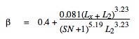
Eventually, in the late 1950s and early 1960s, the AASHO Road Test produced the equivalent single axle load concept. Axle load equivalency has been one of the most widely adopted results of the AASHO Road Test. A variety of equivalency factors can be used depending on the pavement section which is defined by a Structural Number and the terminal serviceability index (for flexible pavements). The basic equation used for calculating AASHTO equivalency factors [after AASHTO, 1981]:
![The basic equation used for calculating AASHTO equivalency factors [after AASHTO, 1981]](https://www.pavementinteractive.org/wp-content/uploads/2008/09/WxW18.jpg)
where
W = axle applications
 = inverse of equivalency factors (where W18 = number of 18,000 lb single axle loads
Lx = axle load
L2 = code for axle configuration
1 = single axle
2 = tandem axle
3 = tridem axle (added in 1986 Guide)
 : a function of the ratio of loss in serviceability at time t to the potential loss taken at a point where pt = 1.5
pt = “Terminal” serviceability index
 : function which determines the general shape of serviceability trend with increasing axle load applications
SN = structural number (formerly called a “thickness index”)
Materials
Some of the earliest recorded information about materials which could be (and were) used in pavements concern hydraulic cement and the Romans; however, in fairness, the earliest known use of hydraulic lime was in Syria about 6,500 B.C. (over 6,000 years before the Romans — give or take a few hundred years) (Brown, 1987). The Romans “discovered” that grinding volcanic tuff with powdered hydraulic lime produced a hydraulic cement (“hydraulic” in that it hardened in the presence of water). The hydraulic lime was produced by heating limestone above 850 °C thereby driving off CO2 and converting the limestone to CaO. The first known use of hydraulic cement by the Romans occurred at about 120 B.C. (in Rome oddly enough). The “best” variety of volcanic tuff was found near the town of Pozzuoli (near Naples on the southwestern coast of Italy) and the material acquired the name of pozzolana. Further, the Romans learned a bit about the use of other additives such as blood, lard and milk. Apparently, blood (hemoglobin actually) is an effective air-entraining agent and plasticizer (given the mild Mediterranean climate the primary use was likely for workability).
With regard to material testing, the year 1898 was significant: the American Society for Testing and Materials (ASTM) was established.
Some of the early paving materials have been previously discussed; however, it might be interesting to compare a few prices. For example, refined Trinidad Lake asphalt in 1893 cost about $27 to $36 per metric ton at the Port of New York. To adjust these costs to contemporary prices one must multiply by at least a factor of ten. Thus, the same cost today would be about $270 to $360 per metric ton (or about twice as much as an asphalt cement binder today) without the product refinements. (Note: original asphalt prices from Byrne in 1896.)
With regard to PCC compressive strength, Byrne reported in 1896 that PCC air cured for six months for a St. Louis bridge had a compressive strength of 8.3 MPa. Other compressive strengths he reported (presumably pre-1890s) ranged from 1.4 MPa (1 month age) to 9.7 MPa (1 year age). Compare these results to contemporary compressive strengths of 34.5 to 137.9 MPa. Thus, in 100 years, PCC strength has increased about 100 times (ratio of extreme low to extreme high).
Byrne also provided some cost data on wood block pavements in London. During the late 1800s, the average cost was estimated to be about $0.70 per m2 per year. In terms of today’s costs, this would be about $7.00 per m2 per year or $26,000 per lane-kilometer per year. If all of the WSDOT highway network (say, 28,800 lane-km) was maintained in a similar cost manner, it would cost about $0.75 billion (over five times as much as today). Add to this the absolutely unacceptable requirement for wood blocks (about 1 billion board-feet per year — assuming an average life of seven years — probably very optimistic with today’s traffic).
It was estimated by Boorman in his 1908 book that about 33,000,000 m2 of “standard asphalt pavement” existed in the U.S. and 85 percent of this used Trinidad Lake asphalt as the binder. This roughly translates to about 2,700,000 metric tons of equivalent hot mix (or about three times the annual amount of hot mix purchased by WSDOT).
Material characterization up to the 1930s tended to focus on basic material parameters such as liquid limit, plasticity index and gradation. The strength or bearing capacity of unstabilized materials was usually discussed in terms of cohesion and friction angle (as illustrated by Collins and Hart, 1936). Goldbeck [1940], in his proposed design method, characterized the subgrade soil in terms of “subgrade supporting value” in units of pounds per square inch (ranging from 0 to 90 psi). The recommended test was to use a bearing block directly on a compacted sample. The test result was a plot of bearing stress versus indentation of the block into the sample. An indentation of 12.5 mm was used as a target value for obtaining the “bearing capacity” or “subgrade supporting value.”
The papers by Burggraf in 1938, 1939, and 1940 summarized the results of extensive field shear tests made on flexible pavement layers. These shear tests were conducted with a small, portable apparatus which used a parabolic plate in contact with the soil being tested [1938]. As an illustration of the results from this test, the measured shear strength of cohesive subgrade soils were evaluated beneath stabilized base courses. The following classes were reported [1939]:
Work by Hubbard and Field [1940] for The Asphalt Institute tended to downplay the importance of subgrade bearing values, and instead, emphasized the importance of surface deflection testing as a way to characterize the overall pavement structure.
The one material characterization test which had a tremendous impact on design and to some extent still does, was the development of the California Bearing Ratio (CBR). Porter of the California Division of Highways stated in a 1942 Highway Research Board paper:
“The bearing ratio test was devised in 1929 in an attempt to eliminate some of the objections to field loading tests and to provide a quick method for comparing local base and subbase materials.”
Some of the positive aspects of the CBR laboratory test as listed by Porter:
- Improvement over field static load tests which must overcome “consolidation deformation” since the CBR specimen is compacted to a density expected in the field. California’s attempts to use static field bearing tests were judged as unsuccessful; hence, the emphasis on correlating pavement performance with a straightforward laboratory test.
- The soaking of the laboratory specimens with a surcharge (which represents the weight of the pavement) permits the material to swell and reach the adverse state of moisture which can exist in the field.
- The penetration test determines the material’s resistance to lateral displacement resulting in a combined measure of the influence of cohesion and internal friction.
- The test provides a quick method of comparing base and subgrade materials.
- By investigating and testing the associated materials, an empirical relationship can be established between CBR values, pavement thickness, and performance.
Figure 5 (from Porter’s paper [1942]) shows typical bearing values (psi) versus penetration (in.) for various materials ranging from “very poor subgrade” (CBR up to 5) to “good crushed rock bases” (CBR of 100). The CBRs are in terms of percentages since the bearing value is divided by 1,000 psi (0.1 penetration) or 1,500 psi (0.2 in. penetration) which represents the bearing value of a crushed rock material (refer to “standard curve 100%” in Figure 5).
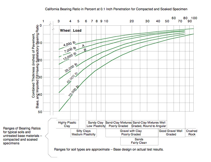
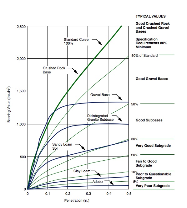 Figure 1.11 (also from Porter [1942]) shows the thickness design curves developed from 12 years of CBR tests associated with both failed and good performing pavements on the California highway system. Curves “A” and “B” show the minimum pavement thicknesses for light and medium-heavy traffic. The additional curves were added by U.S. Army Corps of Engineers for the design of flexible airfield pavements. The tire inflation pressure for the traffic was 400 kPa. The design curves also embody the assumption of the pavement structure lying on compacted soils (at least 300 mm of compacted subgrade). Porter’s paper and a discussion of it by A.C. Benkelman further “reinforced” the concept of limiting pavement deflections for design purposes.
 The use of the triaxial test during the 1930s and 1940s was twofold:
- determination of shear strength (cohesion and f angle), and
- estimation of moduli similar to a modulus of elasticity [Barber, 1946; Worley, 1943, Palmer and Barber, 1940].
Worley in 1943 reported on the use of triaxial testing and modulus of deformation results for Kansas flexible pavement design. In the Kansas tests, samples either 70 by 200 mm or 125 by 350 mm were used depending on the maximum aggregate size. The stress-strain curve from the triaxial test was used to estimate the modulus of deformation. (Worley realized that the slope of the stress-strain was not constant for most pavement materials, hence the term modulus of deformation was used in lieu of modulus of elasticity.) These moduli were used in the formula shown as Note 1 in Table 1.4.
Nijboer [1954] of the then Shell Oil Laboratories and Seed et al. [1955] at the University of California at Berkeley helped to introduce the pavement community to the need for accounting for repeating loadings in the pavement system. Nijboer reported on fatigue of a “sandsheet” wearing course and Seed et al. on repeated loading effects on the strength and deformation of compacted clay.
In summary, the structural design of asphalt and PCC pavements up to the 1950s (where this section stops) was a function of an evolutionary process beginning with the Romans then Telford and Macadam. This evolution accelerated greatly in the 1930s and 1940s as the prior information, hopefully, suggests.
References
- AASHTO, AASHTO Interim Guide for Design of Pavement Structures — 1972 — Chapter III Revised 1981, American Association of State Highway and Transportation Officials, Washington, D.C., 1981.
- Agg, T.R., and C.B. McCullough, “An Investigation of Concrete Roadways,” Technical Report No. 1, Iowa State Highway Commission, Ames, Iowa, May 1, 1916.
- Agg, T.R.,The Construction of Roads and Pavements, McGraw-Hill, New York, 1940.
- Baker, I.O., A Treatise on Roads and Pavements, John Wiley and Sons, New York, 1903.
- Baker, I.O., Roads and Pavements, John Wiley and Sons, New York, 1903.
- Barber, E.S., “Application of Triaxial Compression Test Results to the Calcula¬tion of Flexible Pavement Thickness,” Proceedings, Highway Research Board, Washington, D.C., December 5-8, 1946.
- Baron, F.M., “Variables in the Design of Concrete Runways of Airports,” Pro¬ceedings, Highway Research Board, Washington, D.C., December 1-4, 1942.
- Bateman, J.H., Highway Engineering, John Wiley and Sons, New York, 1928.
- Boorman, T.H., Asphalts, William T. Comstock, New York, 1908.
- Boyd, K., “An Analysis of Wheel Load Limits as Related to Design,” Proceed¬ings, Highway Research Board, Washington, D.C., December 1-4, 1942.
- Bradbury, R.D., Reinforced Concrete Pavements, Wire Reinforcement Institute, Washington, D.C., 1938.
- Burggraf, F., “Field Tests and Sampling Equipment ,” Proceedings, Part II, Highway Research Board, Washington, D.C., November 28-December 2, 1938.
- Burggraf, F., “Field Tests on Bearing Capacity, Shearing and Penetration Resis¬tance of Soils,” Proceedings, Highway Research Board, Washington, D.C., December 3-6, 1940.
- Burggraf, F., “Field Tests on Shearing Resistance,” Proceedings, Highway Research Board, Washington, D.C., December 5-8, 1939.
- Byrne, A.T., A Treatise on Highway Construction, John Wiley and Sons, New York, 1896.
- Coles, J.M., “The World’s Oldest Road,” Scientific American, November 1989.
- Collins, H.J. and C.A. Hart, Principles of Road Engineering, Edward Arnold Publishers, Ltd., London, 1936.
- Crawford, C., “The Rocky Road of Mix Design,” Hot-Mix Asphalt Technology, National Asphalt Paving Association, Washington, D.C.
- Eckels, S., “Distribution of Wheel Loads Through Various Rubber Tires,” Pro¬ceedings, Highway Research Board, Washington, D.C., December 13-14, 1928.
- Gillette, H.P., Economics of Road Construction, The Engineering News Publish¬ing Co., New York, 1906.
- Goldbeck, A.T. “A Method of Design of Non-Rigid Pavements for Highways and Airport Runways,” Proceedings, Highway Research Board, Washington, D.C., December 3-6, 1940.
- Goodyear Tire and Rubber Company, “Successful Commercial Selling,” The Good Year Tire and Rubber Co., Sales Training Department, Cuyahoga Falls, Ohio, 1985.
- Gray, B.E., “Present Design Practice and Construction Developments in Flexible Pavements,” Proceedings, Highway Research Board, Washington, D.C., December 5-8, 1939.
- Hubbard, P., Dust Preventives and Road Binders, John Wiley and Sons, New York, 1910.
- Hveem, F.N. and Carmany, R.M., “The Factors Underlying the Rational Design of Pavements,” Proceedings, Highway Research Board, Washington, D.C., December 7-10, 1948.
- Jaster, J., G.F. Schlesinger, J.S. Crandell, and R.L. Phillips, “Developments in Brick Pavements in the United States,” Public Roads, Volume 19, No. 4,
- Judson, W.P., Road Preservation and Dust Prevention, The Engineering News Publishing Co., New York, 1908.
- Krchma, L.C. and D.W. Gagle, “A U.S.A. History of Asphalt Refined from Crude Oil and Its Distribution,” Proceedings, Association of Asphalt Paving Tech¬nologists, Williamsburg, Virginia, February 1974.
- Leger, A., Les Travaux Publics les Mines et la Metallurgie aux Temps des Romains, Paris, 1875.
- Nijboer, L.W., “Mechanical Properties of Asphalt Materials and Structural Design of Asphalt Roads,” Proceedings, Highway Research Board, January 12-15, Washington, D.C., 1954.
- Oglesby, C.H. and L.I. Hewes, Highway Engineering, Second Edition, John Wiley and Sons, New York, 1962.
- Palmer, L.A. and E.S. Barber, “Soil Displacement Under a Circular Loaded Area,” Proceedings, Highway Research Board, Washington, D.C., December 3-6, 1940.
- Porter, O.J., “Foundations for Flexible Pavements,” Proceedings, Highway Research Board, Washington, D.C., December 1-4, 1942.
- Public Roads Administration, Highway Practice in the United States of America, Public Roads Administration, Federal Works Agency, Washington, D.C., 1949.
- Rose, A.C., When All Roads Led to Rome, Bureau of Public Roads, U.S. Depart¬ment of Agriculture, Washington, D.C., 1935.
- Seed, H.B., C.K. Chan and C.L. Monismith, “Effects of Repeated Loading on the Strength and Deformation of Compacted Clay,” Proceedings, Highway Research Board, Washington, D.C., January 11-14, 1955.
- Smiles, S., Lives of the Engineers — Metcalfe-Telford, John Murray, London, 1904.
- Steele, G.W. and B.F. Himmelman, “A Dynamic Committee in a Century of Change,” ASTM Standardization News, November 1986.
- Tillson, G.W., Street Pavements and Paving Materials, John Wiley and Sons, New York, 1900.
- U.S. Patent Office, Official Gazette of the United States Patent Office, May 5 to June 30, inclusive, Government Printing Office, Washington, D.C., 1903.
- Westinghouse Co., Air Brake Tests, The Westinghouse Air Brake Co., Wilmerd¬ing, Pennsylvania, 1904.
- Worley, H.E., “Triaxial Testing Methods Usable in Flexible Pavement Design,” Proceedings, Highway Research Board, Washington, D.C., November 27-30, 1943.