Proper reinforcing steel placement is crucial to CRCP performance. CRCP failures are usually associated with insufficient reinforcement bar lapping, unconsolidated PCC around the steel, improper position of the steel in the slab and extreme hot weather during construction. In general, CRCP seems to be less forgiving of construction errors than other types of rigid pavement (Burke, 1983[1]). Reinforcing steel for CRCP can be placed by two general methods:
- Manual method
- Mechanical method

Manual Method
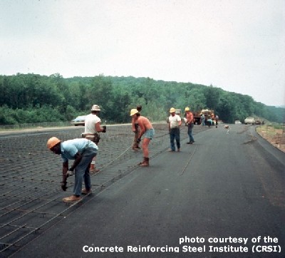
The most common method, the manual method (see Figure 1), involves hand-placing the reinforcing steel before the PCC is placed. Since the steel is located at mid-depth or higher in the finished slab, the reinforcing steel must be supported by small metal or plastic “chairs” in order to achieve this elevation before PCC placement. These chairs must be strong enough to hold the reinforcing steel in place during PCC placement, consolidation and finishing.
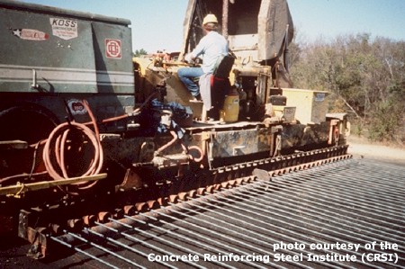
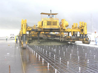
The typical placement process involves (1) placing the transverse bars (which function only as placement aids) on chairs (see Figure 2), (2) arranging the longitudinal bars on top, and then (3) tying the longitudinal bars to the transverse bars. Typically, they are tied or clipped to the transverse bars every 1.2 – 1.8 m (4 – 6 ft.) (Burke, 1983[1]). Figure 3 shows reinforcing bars in their final position before PCC placement.
The chief advantage of the manual method is that it allows for easy checking of bar placement, height and lap distance. However, the manual method is slower and more labor intensive than mechanical methods.
|
|
Mechanical Method
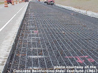
Reinforcing steel can also be placed mechanically. There are many variations of mechanical placement, however most of them involve picking up prepositioned, but not precisely spaced, reinforcing bars with a placer/spreader attachment and then holding the bars at a preset depth as the PCC is placed around them (see Figure 4). However, a number of states have found longitudinal steel placement deviations of ± 75 mm (±3 inches) in the vertical plane when tube feeders were used to position the steel (FHWA, 1990b[2]).

Additionally, CRCP pavements (and JRCP pavements when they were more routinely constructed) can be placed in two lifts. First, the bottom lift is placed, followed by reinforcing bar placement, and then finished with a second PCC lift. Although feasible, this method can be costly as it usually requires two passes of the PCC paver. However, some equipment companies offer pavers capable of placing two lifts simultaneously.
- Burke, J. (1983). Construction of Continuously Reinforced Concrete Pavements. Concrete Reinforcing Steel Institute. Schaumburg, IL.↵
- Federal Highway Administration (FHWA). (1990b). Continuously Reinforced Concrete Pavement. Technical Advisory 5080.14. Federal Highway Administration. Washington, D.C.↵


